3D Point Cloud Projection onto a 2D Image in C++
In robotics and autonomous driving, we often need a 3D reconstruction of the current scene. A common way to obtain it is to use a 3D camera or LiDAR to capture a point cloud—a collection of 3D coordinates that you can think of as an N×3 array (each row is a point).
By analyzing point clouds, we can infer the target location for a robot to grasp, or detect obstacles around an autonomous vehicle. A very common workflow is to take the point cloud and, from a camera’s viewpoint, project it onto a 2D coordinate system for analysis—similar to how a camera captures the 3D world as a 2D image. Doing so can reduce dimensionality and complexity for certain problems.
¶ The Math Behind Coordinate Projection
Projection is essentially matrix multiplication. We use the following equation to transform a point from the world coordinate system (World Coordinate System, an objective viewpoint) into the camera coordinate system (Camera Coordinate System, coordinates as seen from the camera):
$$\begin{bmatrix} u’ \\ v’ \\ w \end{bmatrix} = \mathbf{K} \begin{bmatrix} \mathbf{R} & \mathbf{t} \end{bmatrix} \begin{bmatrix} X_w \\ Y_w \\ Z_w \\ 1 \end{bmatrix}$$
Here, $K$ is a 3×3 matrix that represents the camera’s intrinsic parameters (intrinsics). It is defined as:
$$\mathbf{K} = \begin{bmatrix}
f_x & s & c_x \\
0 & f_y & c_y \\
0 & 0 & 1
\end{bmatrix}$$
Where:
- $f_x, f_y$: focal lengths in the x and y directions
- $c_x, c_y$: principal point (the center of projection on the image) in x and y
- $s$: skew; non-zero indicates optical skew/distortion
In a system, the intrinsics are usually fixed, because the camera parameters should be constants.
$R$ is a 3×3 matrix representing rotation with respect to the camera, and $t$ is a 1×3 translation vector (translation) toward the camera. Together they form a 3×4 matrix that transforms the point using the camera as the origin. This 3×4 matrix is also called the extrinsics.
For example, the following extrinsics represent no rotation (the rotation matrix is identity), and a translation of +20 along the camera coordinate z-axis:
$$\mathbf{Extrinsics} = \begin{bmatrix}
1 & 0 & 0 & 0 \\
0 & 1 & 0 & 0 \\
0 & 0 & 1 & 20
\end{bmatrix}$$
In a system, the extrinsics are variables: they depend on how the observer wants to observe the scene.
Finally, the 3D point in world coordinates is written as a 4D vector $(X_w, Y_w, Z_w, 1)$ because it uses homogeneous coordinates. During projection, we add one extra dimension so that the math works out cleanly.
Now we can compute the new coordinates. Multiply intrinsics and extrinsics, then multiply by the original world coordinate vector, and we obtain a new 3D coordinate $(u’, v’, w)$.
This new coordinate is the projected result from the camera viewpoint, but to place it onto the 2D image plane, we need to normalize it by making the z term equal to 1. Then we get the final 2D coordinates $(u, v)$:
$$u = \frac{u’}{w}, \quad v = \frac{v’}{w}$$
Note that $w$ corresponds to the camera-coordinate Z axis. Besides normalization, you can also keep it as depth information for later use (e.g., coloring).
¶ Code
Here I explain it in C++. You need to install Eigen and OpenCV first—both can be installed via apt or brew, which should be straightforward. Although the example is in C++, the concept is the same in any language or library.
First, define the 3D point cloud, intrinsics, and extrinsics:
std::vector<Eigen::Vector3d> points;   // All 3D points in world coordinates
Eigen::Matrix3d K;                     // Intrinsic matrix
Eigen::Matrix<double, 3, 4> extrinsic; // Extrinsic matrix
Then apply the formula above to project:
std::vector<Eigen::Vector3d> project() {
    std::vector<Eigen::Vector3d> projected;
    Eigen::Matrix<double, 3, 4> projMatrix = K * extrinsic;
    for (const auto &pt : points) {
        Eigen::Vector4d hom(pt.x(), pt.y(), pt.z(), 1.0);
        Eigen::Vector3d projectedPoint = projMatrix * hom;
        double z = projectedPoint.z();
        if (z > 0) {
            // 存入圖片的 x、y 座標,並保留相機視角的 z 資訊,用來之後上色辨識用
            projected.emplace_back(projectedPoint.x() / z, projectedPoint.y() / z, z);
        }
    }
    return projected;
}
This is simply the matrix computation from the equation—nothing particularly special.
Full code:
#include <Eigen/Dense>
#include <iostream>
#include <opencv2/opencv.hpp>
#include <opencv2/viz.hpp>
#include <random> // For random point generation if needed
#include <vector>

class PointCloudTransformer {
  public:
    std::vector<Eigen::Vector3d> points;   // All 3D points in world coordinates
    Eigen::Matrix3d K;                     // Intrinsic matrix
    Eigen::Matrix<double, 3, 4> extrinsic; // Extrinsic matrix

    PointCloudTransformer() {
        // Default camera intrinsics
        K << 800.0, 0.0, 640.0,
             0.0, 800.0, 480.0,
             0.0, 0.0, 1.0;

        // Default extrinsics (camera at origin looking along Z)
        extrinsic << 1, 0, 0, 0,
                     0, 1, 0, 0,
                     0, 0, 1, 100.0; // Move camera along Z

        std::cout << "intrinsic\n" << K << "\n";
        std::cout << "extrinsic\n" << extrinsic << "\n";
    }

    void generateCube(int size = 10, double spacing = 1.2) {
        points.clear();
        for (int x = -size; x <= size; ++x) {
            for (int y = -size; y <= size; ++y) {
                for (int z = -size; z <= size; ++z) {
                    if (std::abs(x) == size || std::abs(y) == size || std::abs(z) == size) { // Surface only
                        points.emplace_back(x * spacing, y * spacing, z * spacing + 10.0);   // Offset in Z
                    }
                }
            }
        }
        std::cout << "Generated " << points.size() << " points.\n";
    }

    void applyTransformation(const Eigen::Affine3d &transform) {
        for (auto &pt : points) {
            pt = transform * pt;
        }
    }

    std::vector<Eigen::Vector3d> project() {
        std::vector<Eigen::Vector3d> projected;
        Eigen::Matrix<double, 3, 4> projMatrix = K * extrinsic;
        for (const auto &pt : points) {
            Eigen::Vector4d hom(pt.x(), pt.y(), pt.z(), 1.0);
            Eigen::Vector3d projectedPoint = projMatrix * hom;
            double z = projectedPoint.z();
            if (z > 0) {
                projected.emplace_back(projectedPoint.x() / z, projectedPoint.y() / z, z);
            }
        }
        return projected;
    }

    void visualize(const std::vector<Eigen::Vector3d> &projected, const std::string &filename = "output.jpg") {
        // find the max and min depth for coloring
        double minDepth = std::numeric_limits<double>::max();
        double maxDepth = std::numeric_limits<double>::lowest();
        for (const auto &pt : projected) {
            if (pt.z() < minDepth)
                minDepth = pt.z();
            if (pt.z() > maxDepth)
                maxDepth = pt.z();
        }
        const double depthRange = maxDepth - minDepth;
        const double cliff = 200.0;

        cv::Mat image(960, 1280, CV_8UC3, cv::Scalar(255, 255, 255)); // White bg
        for (const auto &pt : projected) {
            if (pt.z() > 0) {
                int u = static_cast<int>(pt.x()), v = static_cast<int>(pt.y());

                int depthValue = (depthRange > 0) ? static_cast<int>(cliff * (pt.z() - minDepth) / depthRange) : 128;

                if (u >= 0 && u < image.cols && v >= 0 && v < image.rows) {
                    cv::circle(image, cv::Point(u, v), 2, cv::Scalar(255 - depthValue, depthValue / 2, depthValue), -1);
                }
            }
        }

        // Show 2D projection
        cv::imshow("Projection", image);

        // Create a WCloud object
        cv::Mat cloudMat(points.size(), 1, CV_64FC3);
        cv::Mat colors(points.size(), 1, CV_8UC3);
        for (size_t i = 0; i < points.size(); ++i) {
            cloudMat.at<cv::Vec3d>(i, 0) = cv::Vec3d(points[i].x(), points[i].y(), points[i].z());
            // Color based on depth (projected.z())
            double depth = projected[i].z();
            int depthValue = (depthRange > 0) ? static_cast<int>(255.0 * (depth - minDepth) / depthRange) : 128;
            colors.at<cv::Vec3b>(i, 0) = cv::Vec3b(255 - depthValue, depthValue / 2, depthValue);
        }
        cv::viz::WCloud cloud(cloudMat, colors);
        cloud.setRenderingProperty(cv::viz::POINT_SIZE, 3.0);

        cv::viz::Viz3d window("3D Points");
        window.setBackgroundColor(cv::viz::Color::white());

        // Show the cloud
        window.showWidget("Cloud", cloud);

        // Add coordinate system
        window.showWidget("Coordinate Widget", cv::viz::WCoordinateSystem(20));

        // Keep both windows open and interactive
        while (!window.wasStopped()) {
            int key = cv::waitKey(30);
            if (key == 27) { // ESC key
                break;
            }
            window.spinOnce(30);
        }
    }
};

int main() {
    PointCloudTransformer pct;
    pct.generateCube();

    double angle = M_PI / 6; // 30 degrees in radians
    Eigen::Affine3d rotationY = Eigen::Affine3d(Eigen::AngleAxisd(angle, Eigen::Vector3d::UnitY()));
    Eigen::Affine3d rotationX = Eigen::Affine3d(Eigen::AngleAxisd(angle, Eigen::Vector3d::UnitX()));
    Eigen::Affine3d translation = Eigen::Affine3d(Eigen::Translation3d(2, 1, -5));
    Eigen::Affine3d scaling = Eigen::Affine3d(Eigen::Scaling(1.8));

    Eigen::Affine3d transform = rotationY * rotationX * translation * scaling;
    pct.applyTransformation(transform);

    auto projected = pct.project();
    pct.visualize(projected);

    return 0;
}
This program opens two windows: one for the 2D projected image, and one for the 3D point cloud model.
In the 3D point cloud window, you can rotate the model freely:
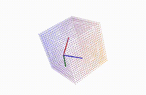
The red axis is X, the green axis is Y, and the blue axis is Z. After aligning the 3D model axes with the image coordinate system (the image uses the top-left corner as the origin), you will see that the views match, which also confirms that the projection is correct.
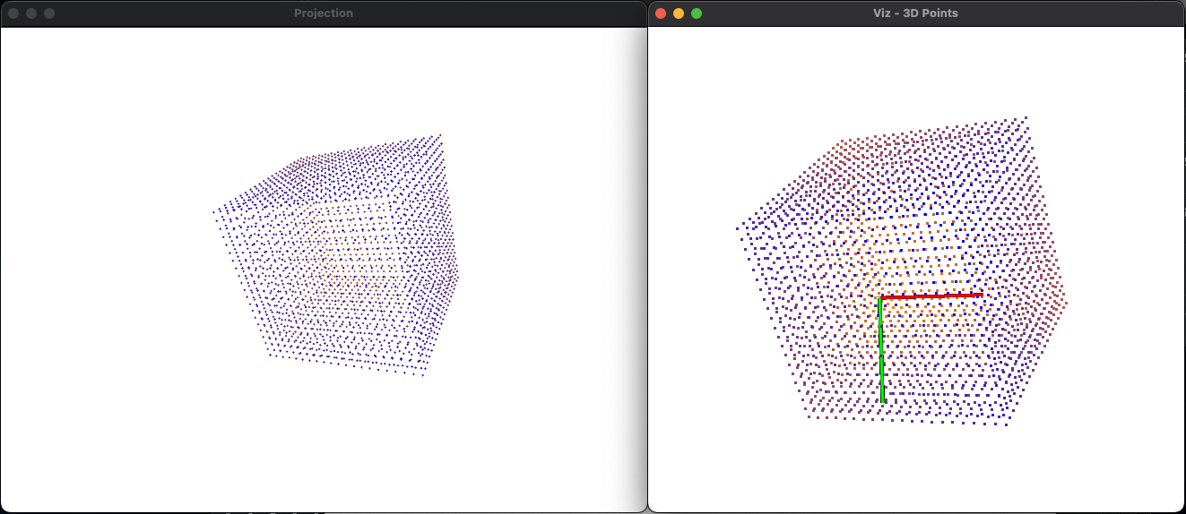
(Left: image, right: point cloud)
I recommend running the code yourself. The current point cloud is a cube, but you can also generate point clouds of other shapes and experiment!