C++で3D点群を2D画像へ投影する
ロボティクスや自動運転の分野では、現在のシーン(scene)の3D復元を把握するために、3DカメラやLiDARで点群(point cloud)を取得することがよくあります。点群は、3次元座標の集合であり、実装上は N×3 の配列(各行が1点)として扱えることが多いです。
点群を解析することで、ロボットが把持すべき対象の位置を推定したり、自動運転車の周囲の障害物を検出したりできます。よく使われるアプローチの1つが、点群を「あるカメラ視点」から2D座標系へ投影し、その2D上で解析することです。これは、3D世界をカメラで撮影して2D画像にするのと同じで、問題によっては次元が下がり、複雑さを減らせます。
¶ 座標投影の数学
座標の投影は基本的に行列演算です。以下の式で、世界座標系(World Coordinate System:客観視点)からカメラ座標系(Camera Coordinate System:カメラ視点)へ点を変換します:
$$\begin{bmatrix} u’ \\ v’ \\ w \end{bmatrix} = \mathbf{K} \begin{bmatrix} \mathbf{R} & \mathbf{t} \end{bmatrix} \begin{bmatrix} X_w \\ Y_w \\ Z_w \\ 1 \end{bmatrix}$$
ここで $K$ は 3×3 行列で、カメラの内部パラメータ(intrinsics)です。定義は次のとおりです:
$$\mathbf{K} = \begin{bmatrix}
f_x & s & c_x \\
0 & f_y & c_y \\
0 & 0 & 1
\end{bmatrix}$$
各項の意味は以下です:
- $f_x, f_y$: x・y方向の焦点距離(focal length)
- $c_x, c_y$: 画像上の投影中心(principal point)
- $s$: スキュー(skew)。0でない場合、光学的な歪み(skew)を表す
intrinsics はシステム上ほぼ固定であることが多いです。カメラ固有のパラメータは定数として扱えるからです。
$R$ は 3×3 行列で回転(rotation)を表し、$t$ は 1×3 の並進(translation)ベクトルです。これらをまとめた 3×4 行列が、カメラ原点への変換(transformation)を表し、一般に extrinsics と呼ばれます。
例えば、次の extrinsics は回転なし(左側の回転行列が単位行列)で、カメラ座標系の z 軸方向に +20 平行移動することを意味します:
$$\mathbf{Extrinsics} = \begin{bmatrix}
1 & 0 & 0 & 0 \\
0 & 1 & 0 & 0 \\
0 & 0 & 1 & 20
\end{bmatrix}$$
extrinsics は観測者がどのように観測するかに依存する変数です。
最後に、世界座標系の3D点が4次元ベクトル $(X_w, Y_w, Z_w, 1)$ として表されているのは、同次座標(homogeneous coordinates)を使っているためです。投影の数式を成立させるため、次元を1つ増やして表現します。
以上で新しい座標が計算できます。intrinsics と extrinsics を掛け合わせ、世界座標ベクトルに掛けることで、カメラ視点の 3D 座標 $(u’, v’, w)$ を得ます。
ただし画像へ投影するには 2D 座標が必要なので、z を 1 に正規化して、最終的な 2D 座標 $(u, v)$ を得ます:
$$u = \frac{u’}{w}, \quad v = \frac{v’}{w}$$
$w$ はカメラ座標系の Z 軸に相当します。正規化に使うだけでなく、深度情報として保持し(例:色付け)、後段処理に利用できます。
¶ プログラム
ここでは C++ で説明します。事前に Eigen と OpenCV をインストールしてください。いずれも apt や brew で入れられるので比較的簡単です。例は C++ ですが、概念はどの言語・ライブラリでも同じです。
まず、3D点群・intrinsics・extrinsics を定義します:
std::vector<Eigen::Vector3d> points;   // All 3D points in world coordinates
Eigen::Matrix3d K;                     // Intrinsic matrix
Eigen::Matrix<double, 3, 4> extrinsic; // Extrinsic matrix
前述の式どおりに投影を行います:
std::vector<Eigen::Vector3d> project() {
    std::vector<Eigen::Vector3d> projected;
    Eigen::Matrix<double, 3, 4> projMatrix = K * extrinsic;
    for (const auto &pt : points) {
        Eigen::Vector4d hom(pt.x(), pt.y(), pt.z(), 1.0);
        Eigen::Vector3d projectedPoint = projMatrix * hom;
        double z = projectedPoint.z();
        if (z > 0) {
            // 存入圖片的 x、y 座標,並保留相機視角的 z 資訊,用來之後上色辨識用
            projected.emplace_back(projectedPoint.x() / z, projectedPoint.y() / z, z);
        }
    }
    return projected;
}
基本的には、式に従って行列演算をしているだけです。
完全なコード:
#include <Eigen/Dense>
#include <iostream>
#include <opencv2/opencv.hpp>
#include <opencv2/viz.hpp>
#include <random> // For random point generation if needed
#include <vector>

class PointCloudTransformer {
  public:
    std::vector<Eigen::Vector3d> points;   // All 3D points in world coordinates
    Eigen::Matrix3d K;                     // Intrinsic matrix
    Eigen::Matrix<double, 3, 4> extrinsic; // Extrinsic matrix

    PointCloudTransformer() {
        // Default camera intrinsics
        K << 800.0, 0.0, 640.0,
             0.0, 800.0, 480.0,
             0.0, 0.0, 1.0;

        // Default extrinsics (camera at origin looking along Z)
        extrinsic << 1, 0, 0, 0,
                     0, 1, 0, 0,
                     0, 0, 1, 100.0; // Move camera along Z

        std::cout << "intrinsic\n" << K << "\n";
        std::cout << "extrinsic\n" << extrinsic << "\n";
    }

    void generateCube(int size = 10, double spacing = 1.2) {
        points.clear();
        for (int x = -size; x <= size; ++x) {
            for (int y = -size; y <= size; ++y) {
                for (int z = -size; z <= size; ++z) {
                    if (std::abs(x) == size || std::abs(y) == size || std::abs(z) == size) { // Surface only
                        points.emplace_back(x * spacing, y * spacing, z * spacing + 10.0);   // Offset in Z
                    }
                }
            }
        }
        std::cout << "Generated " << points.size() << " points.\n";
    }

    void applyTransformation(const Eigen::Affine3d &transform) {
        for (auto &pt : points) {
            pt = transform * pt;
        }
    }

    std::vector<Eigen::Vector3d> project() {
        std::vector<Eigen::Vector3d> projected;
        Eigen::Matrix<double, 3, 4> projMatrix = K * extrinsic;
        for (const auto &pt : points) {
            Eigen::Vector4d hom(pt.x(), pt.y(), pt.z(), 1.0);
            Eigen::Vector3d projectedPoint = projMatrix * hom;
            double z = projectedPoint.z();
            if (z > 0) {
                projected.emplace_back(projectedPoint.x() / z, projectedPoint.y() / z, z);
            }
        }
        return projected;
    }

    void visualize(const std::vector<Eigen::Vector3d> &projected, const std::string &filename = "output.jpg") {
        // find the max and min depth for coloring
        double minDepth = std::numeric_limits<double>::max();
        double maxDepth = std::numeric_limits<double>::lowest();
        for (const auto &pt : projected) {
            if (pt.z() < minDepth)
                minDepth = pt.z();
            if (pt.z() > maxDepth)
                maxDepth = pt.z();
        }
        const double depthRange = maxDepth - minDepth;
        const double cliff = 200.0;

        cv::Mat image(960, 1280, CV_8UC3, cv::Scalar(255, 255, 255)); // White bg
        for (const auto &pt : projected) {
            if (pt.z() > 0) {
                int u = static_cast<int>(pt.x()), v = static_cast<int>(pt.y());

                int depthValue = (depthRange > 0) ? static_cast<int>(cliff * (pt.z() - minDepth) / depthRange) : 128;

                if (u >= 0 && u < image.cols && v >= 0 && v < image.rows) {
                    cv::circle(image, cv::Point(u, v), 2, cv::Scalar(255 - depthValue, depthValue / 2, depthValue), -1);
                }
            }
        }

        // Show 2D projection
        cv::imshow("Projection", image);

        // Create a WCloud object
        cv::Mat cloudMat(points.size(), 1, CV_64FC3);
        cv::Mat colors(points.size(), 1, CV_8UC3);
        for (size_t i = 0; i < points.size(); ++i) {
            cloudMat.at<cv::Vec3d>(i, 0) = cv::Vec3d(points[i].x(), points[i].y(), points[i].z());
            // Color based on depth (projected.z())
            double depth = projected[i].z();
            int depthValue = (depthRange > 0) ? static_cast<int>(255.0 * (depth - minDepth) / depthRange) : 128;
            colors.at<cv::Vec3b>(i, 0) = cv::Vec3b(255 - depthValue, depthValue / 2, depthValue);
        }
        cv::viz::WCloud cloud(cloudMat, colors);
        cloud.setRenderingProperty(cv::viz::POINT_SIZE, 3.0);

        cv::viz::Viz3d window("3D Points");
        window.setBackgroundColor(cv::viz::Color::white());

        // Show the cloud
        window.showWidget("Cloud", cloud);

        // Add coordinate system
        window.showWidget("Coordinate Widget", cv::viz::WCoordinateSystem(20));

        // Keep both windows open and interactive
        while (!window.wasStopped()) {
            int key = cv::waitKey(30);
            if (key == 27) { // ESC key
                break;
            }
            window.spinOnce(30);
        }
    }
};

int main() {
    PointCloudTransformer pct;
    pct.generateCube();

    double angle = M_PI / 6; // 30 degrees in radians
    Eigen::Affine3d rotationY = Eigen::Affine3d(Eigen::AngleAxisd(angle, Eigen::Vector3d::UnitY()));
    Eigen::Affine3d rotationX = Eigen::Affine3d(Eigen::AngleAxisd(angle, Eigen::Vector3d::UnitX()));
    Eigen::Affine3d translation = Eigen::Affine3d(Eigen::Translation3d(2, 1, -5));
    Eigen::Affine3d scaling = Eigen::Affine3d(Eigen::Scaling(1.8));

    Eigen::Affine3d transform = rotationY * rotationX * translation * scaling;
    pct.applyTransformation(transform);

    auto projected = pct.project();
    pct.visualize(projected);

    return 0;
}
このプログラムは2つのウィンドウを開きます。1つは2D投影画像、もう1つは3D点群モデルです。
3D点群のウィンドウでは、モデルを自由に回転できます:
赤軸がX、緑軸がY、青軸がZです。3Dモデルの座標軸を画像の座標系(画像は左上が原点)に合わせると、見え方が一致することが分かり、投影が正しいことの確認にもなります。
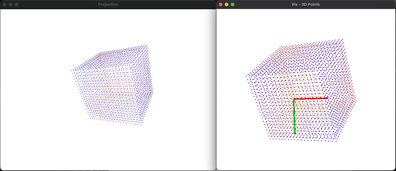
(左:画像、右:点群)
ぜひ実際にコードを動かしてみてください。点群は今は立方体ですが、形状を変えていろいろ試すのも面白いと思います!